目录
| 银杏科技有限公司旗下技术文档发布平台 | |||
| 技术支持电话 | 0379-69926675-801 | ||
| 技术支持邮件 | Gingko@vip.163.com | ||
| 版本 | 日期 | 作者 | 修改内容 |
|---|---|---|---|
| V1.0 | 2020-07-29 | gingko | 初次建立 |
STM32CubeMX教程五十六——Modbus-RTU实验
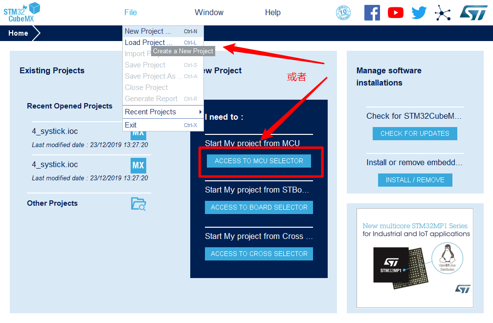
1.在主界面选择File–>New Project 或者直接点击ACCEE TO MCU SELECTOR
 2.出现芯片型号选择,搜索自己芯片的型号,双击型号,或者点击Start Project进入配置
在搜索栏的下面,提供的各 种查找方式,可以选择芯片内核,型号,等等,可以帮助你查找芯片。本实验选取的芯片型号为:STM32H750IBKx。
2.出现芯片型号选择,搜索自己芯片的型号,双击型号,或者点击Start Project进入配置
在搜索栏的下面,提供的各 种查找方式,可以选择芯片内核,型号,等等,可以帮助你查找芯片。本实验选取的芯片型号为:STM32H750IBKx。
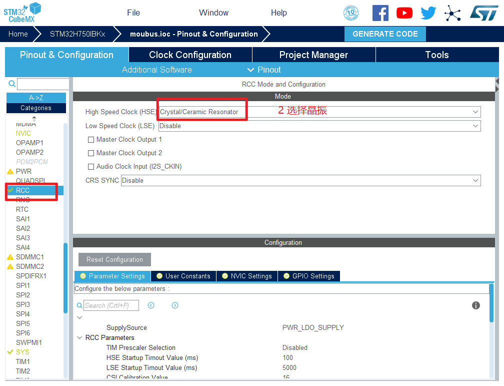
 3.配置RCC,使用外部时钟源
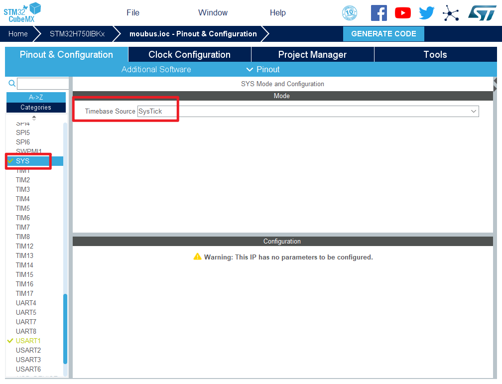
 4.时基源选择SysTick
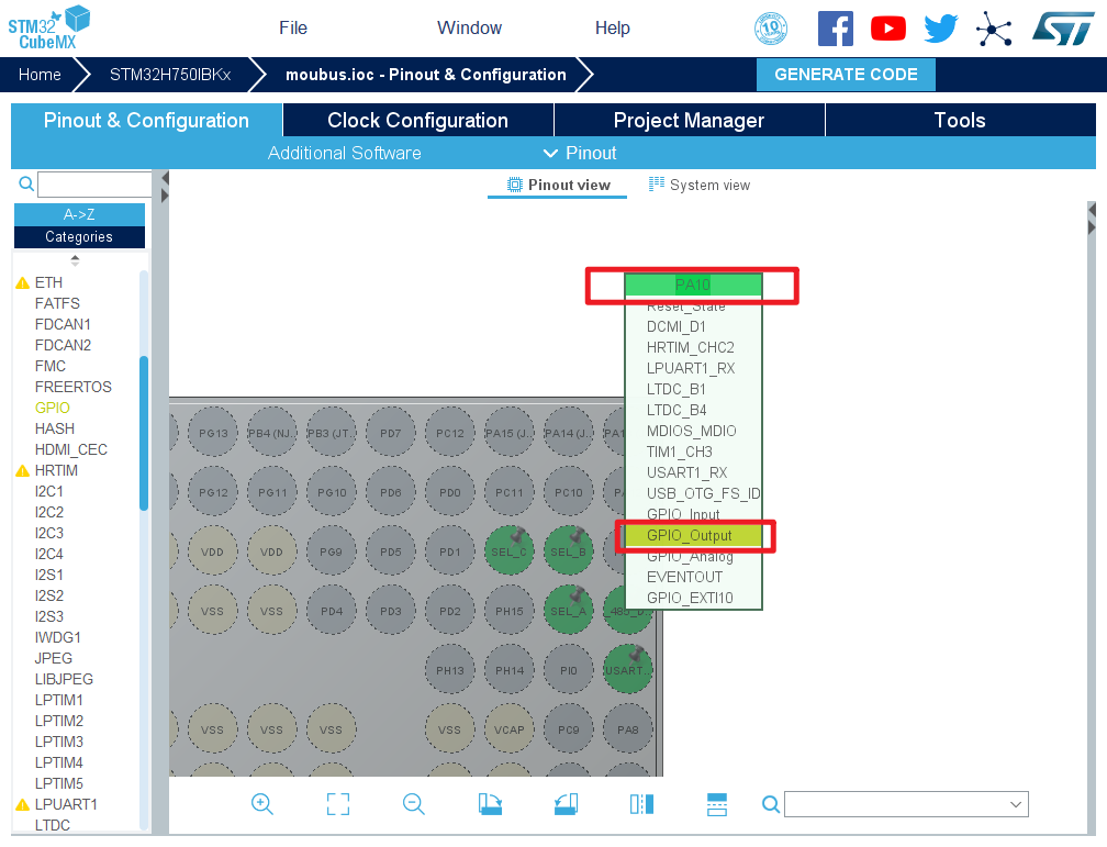
 5.将PA10,PB7,PB8设置为GPIO_Output
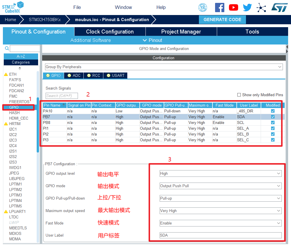
 6.引脚模式配置
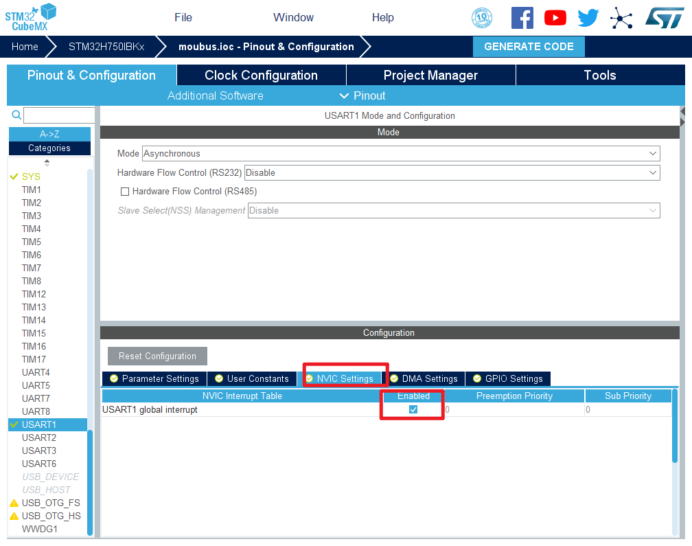
 7.配置串口
 在NVIC Settings一栏使能接收中断
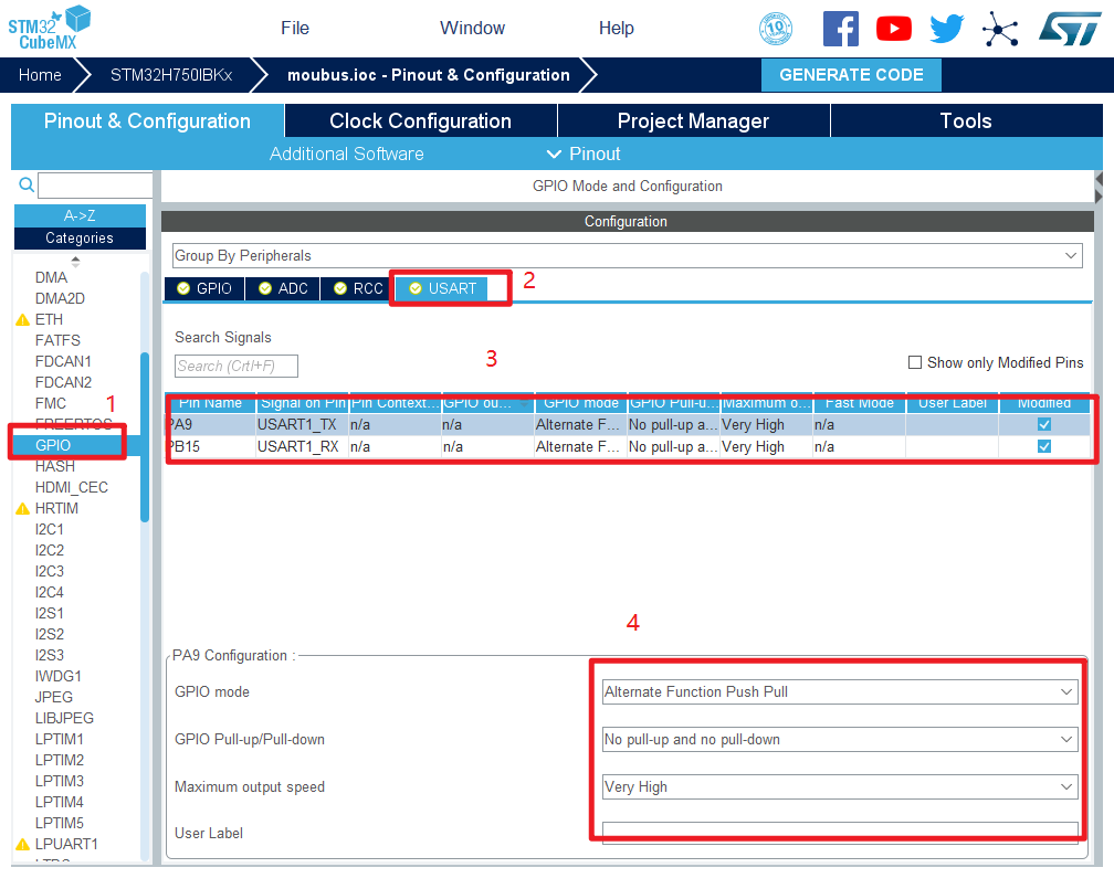
 引脚配置
引脚配置
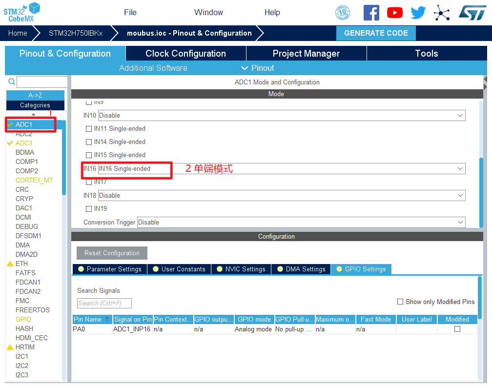
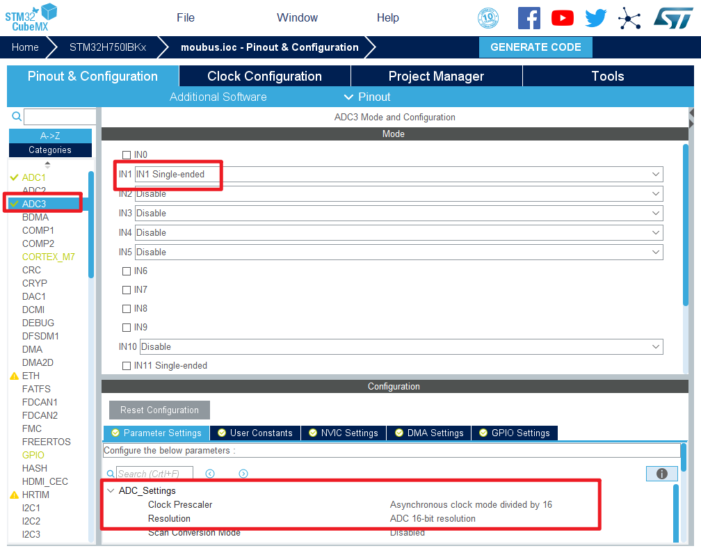
 8.配置ADC
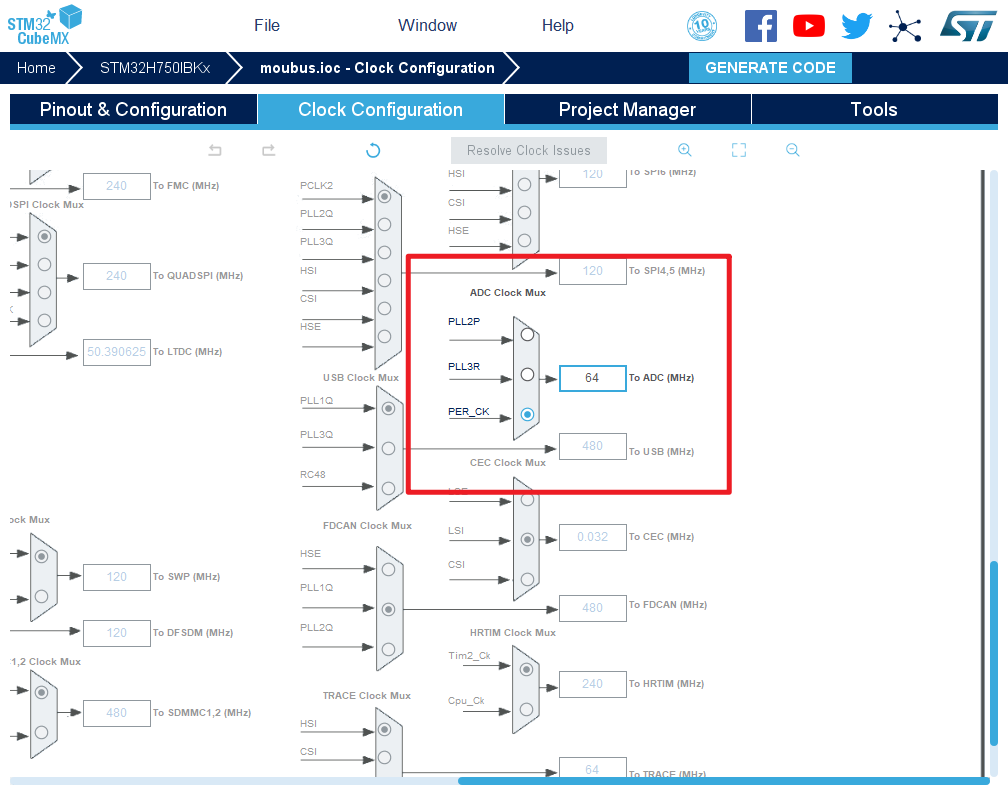
 9.时钟源设置,选择外部高速时钟源,配置为最大主频

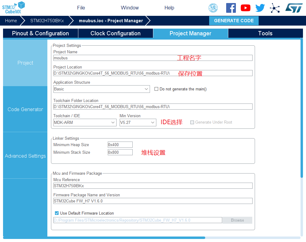
 10.工程文件的设置, 这里就是工程的各种配置 我们只用到有限几个,其他的默认即可 IDE我们使用的是 MDK V5.27
 11.点击Code Generator,进行进一步配置

- Copy all used libraries into the project folder
- 将HAL库的所有.C和.H都复制到所建工程中
- 优点:这样如果后续需要新增其他外设又可能不再用STM32CubeMX的时候便会很方便
- 缺点:体积大,编译时间很长
- Copy only the necessary library files
- 只复制所需要的.C和.H(推荐)
- 优点:体积相对小,编译时间短,并且工程可复制拷贝
- 缺点:新增外设时需要重新用STM32CubeMX导入
- Add necessary library files as reference in the toolchain project configuration file
- 不复制文件,直接从软件包存放位置导入.C和.H
- 优点:体积小,比较节约硬盘空间
- 缺点:复制到其他电脑上或者软件包位置改变,就需要修改相对应的路径
- 自行选择方式即可
- Generate peripheral initialization as a pair of ‘.c/.h’ files per peripheral
- 每个外设生成单独的.c和.h文件
- Backup previously genareated files when re-generating
- 重新生成时备份以前产生的文件
- Keep User Code when re-generating
- 重新生成时保留用户代码
- Delete previously generated files when not re-generated
- 重新生成时删除以前生成的文件
- Set all free pins as analog (to optimize the power consumption)
- 没用到的引脚设置为模拟状态
12.然后点击GENERATE CODE 创建工程
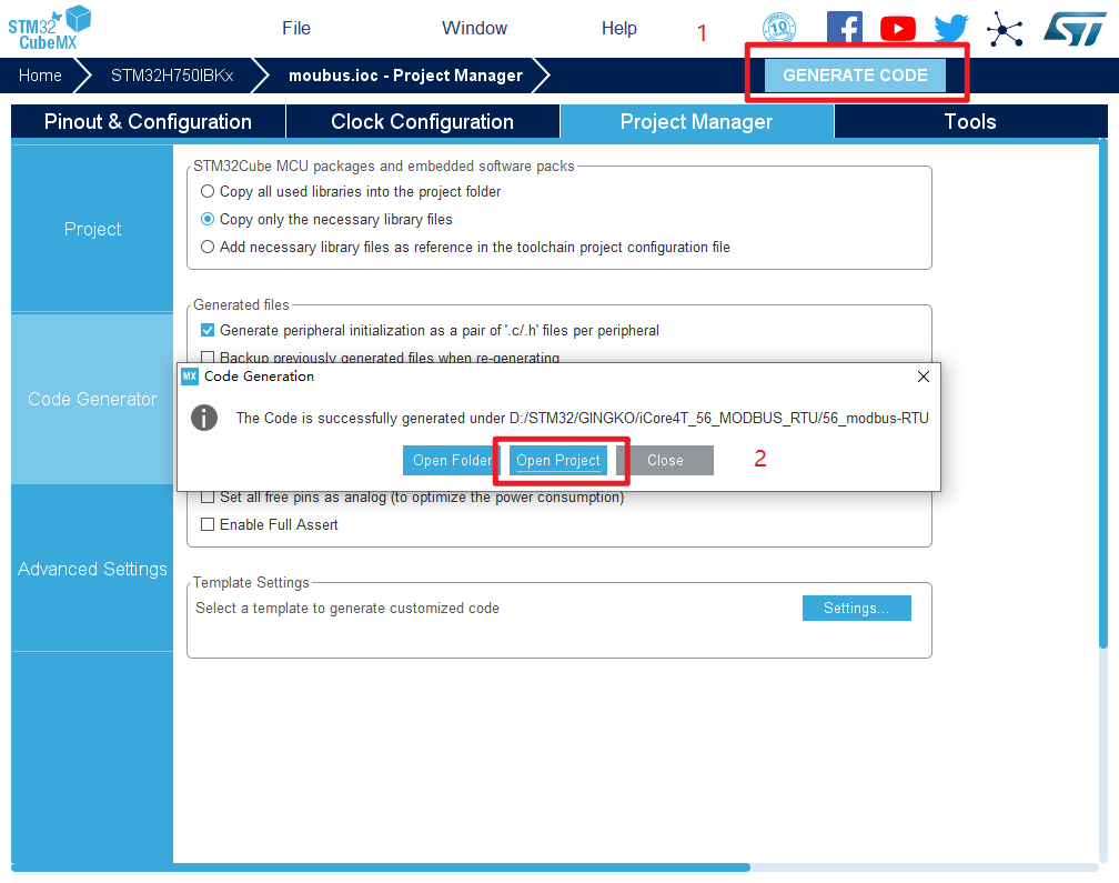 创建成功,打开工程。
实验五十六:Modbus-RTU实验——电源温度监控
一、实验目的与意义
- 了解STM32的UART结构。
- 了解STM32的UART特征。
- 掌握STM32的UART的使用方法。
- 掌握STM32的ADC的使用方法。
- 掌握RS-485的使用方法。
- 掌握Modbus-RTU的使用方法。
- 掌握KEIL MDK 集成开发环境使用方法。
二、实验设备及平台
三、实验原理
1.MODBUS协议介绍
- Modbus是由Modicon(现为施耐德电气公司的一个品牌)在1979年发明的,是全球第一个真正用于工业现场的总线协议。
- Modbus网络是一个工业通信系统,由带智能终端的可编程序控制器和计算机通过公用线路或局部专用线路连接而成。其系统结构既包括硬件、也包括软件。
- Modbus协议是应用于电子控制器上的一种通信语言。通过此协议,控制器互相之间、控制器经由网络和其它设备之间可以通信。它已经成为一通用工业标准。不同厂商生产的控制设备可以连成工业网络,进行集中监控。
- Modbus是OSI模型第七层上的应用层报文传输协议,它在连接至不同类型总线或网络的设备之间提供客户机、服务器通信。
| 层数 | OSI模型 | 对应协议或硬件 |
| 7 | 应用层 | Modbus协议 |
| 6 | 表示层 | 空 |
| 5 | 会话层 | 空 |
| 4 | 传输层 | 空 |
| 3 | 网络层 | 空 |
| 2 | 数据链路层 | Modbus串行链路协议 |
| 1 | 物理层 | RS-485/RS-232 |
- Modbus串行链路协议是一个主/从协议,该协议位于OSI模型的第二层。一个主从类型的系统有一个向某个“子”节点发出显式命令并处理响应的节点(主节点)。典型的子节点在没有收到主节点的请求时并不主动发送数据,也不与其它子节点通信,简单来说就是子节点只听老大的命令,也不与其它同事交流。
- 在物理层,可以使用的物理接口是:RS485和RS232,最常用的是TIA/EIA-485(RS485)两线制接口。
- MODBUS主/从协议原理:
- Modbus串行链路协议是一个主-从协议,在同一时刻,只有一个主节点,一个或多个子节点连接于同一串行总线。子节点不会主动发送数据,只有在收到来自主节点的请求时才会发送,主节点在同一时刻只会发起一个Modbus事务处理。
- 为了方便理解,我们将主节点以及子节点分别称为主设备和从设备。
- 主设备可单独与从设备通信,也能以广播方式和所有从设备通信。如果是单独通信,从设备返回一消息作为回应;如果是广播方式查询的,则不作任何回应。
- 当数据帧到达终端设备(从设备)时,它通过一个简单的“端口”进入被寻址到的设备,该设备去掉数据帧的“信封”(数据头),读取数据,如果没有错误,就执行数据所请求的任务,然后将自己生成的数据加入到取得的“信封”中,把数据帧返回给发送者。返回的响应数据中包含了以下内容:终端从机地址、被执行了的命令、执行命令生成的被请求数据和一个校验码。发生任何错误都不会有成功的响应,或者返回一个错误指示帧。
- MODBUS消息帧:
- Modbus协议定义了一个与基础通信层无关的简单协议数据单元(PDU)。特定总线或网络上的Modbus协议映射能够在应用数据单元(ADU)上引入一些附加域。
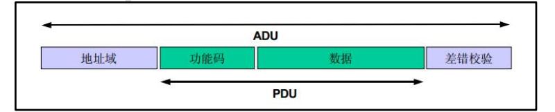
- 地址域在帧的开始部分,由一个字节(8位二进制)组成,十进制位0~255,在我们系统中只使用1~147,其它地址保留。这些位标明了用户指定的从设备的地址,该设备将接受来自与之相连主设备数据。每个从设备的地址必须是唯一的,仅仅被寻址到的从设备会响应包含了该地址的查询。当从设备发送回一个响应,响应中的从设备地址数据便告诉了主设备是哪台设备与之进行通信。
- 功能码的作用是指明从设备要执行的动作。
- 数据域包括附加信息,从设备使用这个信息执行功能码定义的操作。这个域还包括离散项目和寄存器地址、处理的项目数量以及域中的实际数据字节数。在某种请求中,数据域可以是不存在的(0长度),在此情况下服务器不需要任何附加信息,功能码仅说明操作。
- 错误校验域是对报文内容执行“冗余校验”的计算结果。根据不同的传输模式(RTU或ASCII)使用两种不同的计算方法。
- 传输模式:
- 控制器能设置为两种传输模式(ASCII和RTU)中的任何一种在标准的Modbus网络通信。用户选择想要的模式,包括串口通信参数(波特率、校验方式等),在配置每个控制器的时候,在一个Modbus网络上所有设备都必须选择相同的传输模式和串口参数。
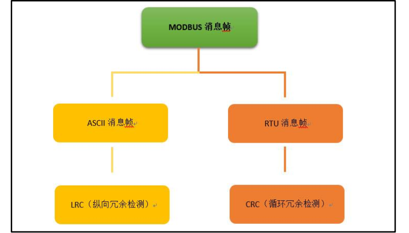
- 当设备使用RTU(RemoteTerminal Unit)模式在Modbus串行链路通信,消息中每个8位域都是一个两个十六进制字符组成。该模式的主要优点是较高的数据密度,在相同的波特率下比ASCII模式有更高的吞吐率。RTU模式的每个报文必须以连续的字符流传送。
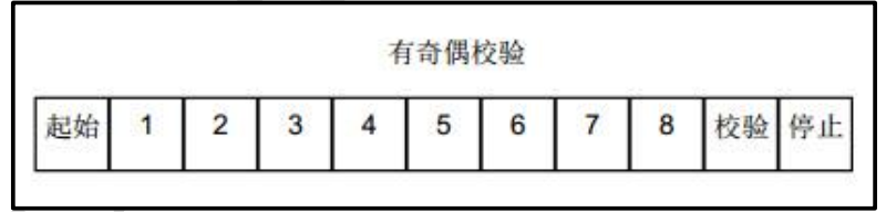
RTU模式每个字节(11位)的格式为:
- 编码系统:8位二进制,报文中每个8位字节含有两个4位十六进制字符(0-9,A-F)。
- 每字节bit流:1起始位、8数据位,首先发送最低有效位、1位奇偶检验、1停止位。
- 偶校验是要求的,其它模式(奇校验、无校验)也可以使用,为了保证兼容性,同时支持无校验模式是建议的。默认校验模式模式必须为偶校验。
- 字符如何串行传送:
- 每个字符或字节均由此顺序发送(从左到右),最低有效位(LSB)…最高有效位(MSB)。

- 设备配置为奇校验、偶校验或无校验都可以接受,如果无奇偶校验,就传送一个附加的停止位以填充字符帧。
- 帧检验域:
- 循环冗余检验(CRC)。
- 帧描述:
| 子字节地址 | 功能代码 | 数据 | CRC |
| 1字节 | 1字节 | 0到252字节 | 2字节 |
* Modbus报文RTU帧
- 由发送设备将Modbus报文构造为带有已知起始和结束标记的帧。这使设备可以在报文的开始接收新帧,并且知道何时报文结束。不完整的报文必须能够被检测到,而错误标志必须作为结果被设置。
- 在RTU模式中,报文帧由时长至少为3.5个字符时间的空闲间隔区分。在后续部分,这个时间区间被称为t3.5。

- 整个报文帧必须以连续的字符流发送。
- 如果两个字符直接的空闲间隔大于1.5个字符时间,则报文被认为不完整应该被接收设备丢弃,如下图。

- 注:RTU接受驱动程序的实现,由于t1.5和t3.5的定时,隐含了大量的对中断的管理。在高速通信速率下,这导致CPU负担加重。因此,在通信速率等于或低于19200bps时,这两个定时必须严格遵守;对于波特率大于19200bps的情形,应该使用2个定时的固定值:建议的字符间超时时间(t1.5)位750us,帧间的超时时间(t1.5)位1.750ms。
- 下图表示了对RTU传输模式状态图的描述。“主设备”和“从设备”的不同角度均在相同的图中表示:

- 从“初始”态到“空闲”态转换需要t3.5定时超时:这保证帧间延迟。
- “空闲”态是没有发送和接收报文要处理的正常状态。
- 在RTU模式,当没有活动的传输的实际间隔打达3.5个字符长时,通信链路被认为在“空闲”态。
- 在链路空闲时,在链路上检测到的任何传输的字符都被识别为帧起始。链路变为“活动”状态。然后,当链路上没有字符传输的时间间隔达到t3.5后,被识别为帧结束。
- 检测到帧结束后,完成CRC计算和校验。然后,分析地址域以确定帧是否发往此设备,如果不是,则丢弃此帧。为了减少接收处理时间,地址域可以在一接到就分析,而不需要等到整个帧结束。这样,CRC计算只需要在帧寻址到该节点(包括广播帧)时进行。
- CRC计算:
- 在RTU模式包含一个对全部报文内容执行的,基于循环冗余校验(CRC-Cyclical Redundancy Checking)算法的错误检验域。CRC域检验整个报文的内容。不管报文有无奇偶校验,均执行此检验。
- CRC包含由两个8位字节组成的一个16位值。
- CRC域作为报文的最后的域附加在报文之后。计算后,首先附加低字节。然后是高字节。CRC高字节为报文发送的最后一个字节。
- 附加在报文后面的CRC的值由发送设备计算。接收设备在接收报文时重新计算CRC的值,并将计算结果于实际接收到的CRC值相比较,如果两个值不相等,则为错误。
- CRC的计算,开始对一个16位寄存器预装全“1”,然后将报文中连续的8位字节对其进行后续的计算。只有字符中的8个数据位参与到生成CRC的运算,起始位、停止位和校验位不参与CRC计算。
- CRC生成的过程中,每个8位字符与寄存器中的值异或,然后结果向最低有效位(LSB)方向移动1位,而最高有效位(MSB)置0.然后提取并检查LSB:如果LSB为1,则寄存器中的值与一个固定的预置值异或;如果LSB为0,则不进行异或操作。
- 这个过程将重复直到执行完8次移位,完成最后一次(第八次)移位及相关操作后,下一个8位字节与寄存器的当前值异或,然后又同上面描述过的一样重复8次。当所有报文中字节都预算之后得到的寄存器中的最终值,就是CRC。
- Modbus功能码定义:
- 三类功能码分别为:公共功能码、用户定义功能码、保留功能码。

- 公共功能码:
- 是较好地被定义的功能码,保证是唯一的,MODBUS组织可改变的,公开证明的,具有可用的一致性测试,MB IETF RFC中证明的,包含已被定义的公共指配功能码和未来使用的未指配保留功能码。
- 用户定义功能码:
- 有两个用户定义功能码的定义范围,即65至72和十进制100至110,用户没有MODBUS组织的任何批准就可以选择和实现一个功能码,不能保证被选功能码的使用是唯一的,如果用户要重新设备功能作为一个公共功能码,那么用户需要启动RFC,以便将改变引入公共分类中,并且指配一个新的公共功能码
- 保留功能码:
- 一些公司对传统产品通常使用的功能码,并且对公共使用是无效的功能码。
- 公共功能码定义:
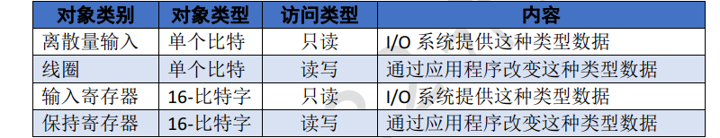
- Modbus数据模型有四种,通过不同的功能码来读写这些数据对象。
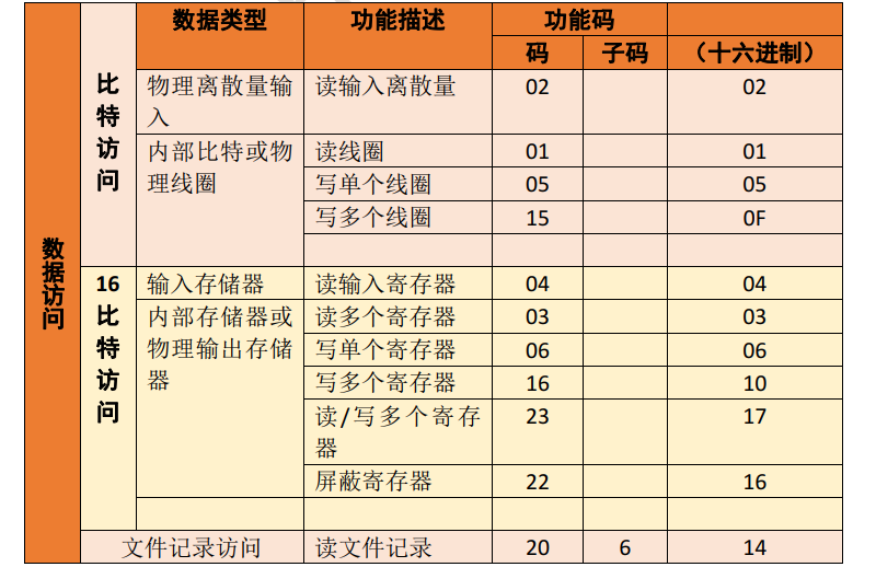

- 常用功能码描述:
- 读线圈寄存器01H:
- 在一个远程设备中,使用该功能码读取线圈的1至2000连续状态。指令列表详细说明了起始地址,即指定的第一个线圈地址和线圈编号。从零开始寻找线圈,因此寻址线圈1-16为0-15。
- 根据数据域的每个比特将响应报文中的线圈分成一个线圈。指示状态1=ON和0=OFF。第一个数据字节的LSB(最低有效位)包括在询问中寻址的输出。其它线圈依次类推,一直到这个字节的高位端为止,并在后续字节中从低位到高位的顺序。
- 如果返回的输出数量不是八的倍数,将用零填充最后字节中的剩余比特(一直到字节的高位端)。字节数量域说明了数据的完整字节数。
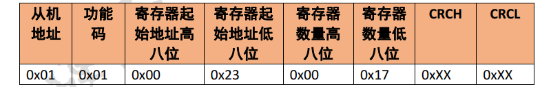
- 指令:
- 例如从机地址为01H,线圈寄存器的起始地址为0023H,结束地址为0038H,总共读取21个线圈,协议如下
- 响应:
- 回数据的每一位对应线圈状态,1=ON、0=OFF,如下

- 在上表中Data1表示0x0023-0x002a的线圈状态,Data1的最低位代表低地址的线圈状态,可以理解为小端模式:

- Data2表示地址0x002b-0x0033的线圈状态,如下表:

- Data3表示地址0x0034-0x0038的线圈状态,不够8位,字节高位填充0,如下:

- 读离散输入寄存器02H:
- 该功能码作用是读离散输入寄存器,位操作,可读单个或多个,协议类似功能码0x01,具体的就不讲解了,参考0x01功能码即可。
- 读保持寄存器03H:
- 读保存寄存器,字节指令操作,可读单个或多个。
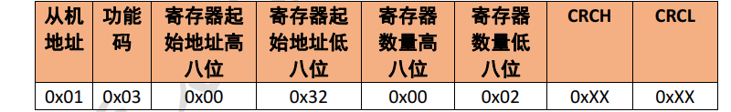
- 指令
- 发送指令从机地址0x01,保存寄存器起始地址0x0032,读2个保存寄存器。
- 响应
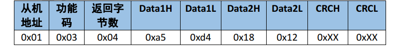
- 数据存储顺序

- 输入寄存器04H:
- 读输入寄存器,字节指令操作,可读单个或多个。发送指令以及响应都和03H一样。
- 写单个线圈寄存器05H:
- 写单个线圈,位操作,只能写一个,写0xff00表示设置线圈状态为ON,写0x0000表示设置线圈状态为OFF。
- 指令
- 设置0x0032线圈位ON

- 响应
- 和发送指令相同。
- 写单个保持寄存器06H
- 写单个保持寄存器,字节指令操作,只能写一个。
- 指令
- 写0x0032保持寄存器为0x1232

- 响应
- 和发送指令相同。
- 写多个线圈寄存器0FH:
- 写多个线圈寄存器,若数据区的某位值为“1”表示被请求的相应线圈状态为ON,若某位值为“0”,则状态为OFF。
- 指令
- 线圈地址为0x04a5,写12个线圈
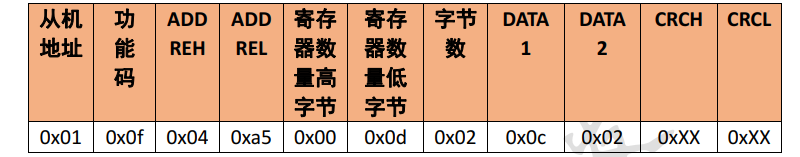
- 上表格中的DATA1为0x0c,表示:

- DATA2为0x02,不够8位,字节高位填充0

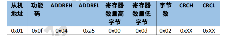
- 响应
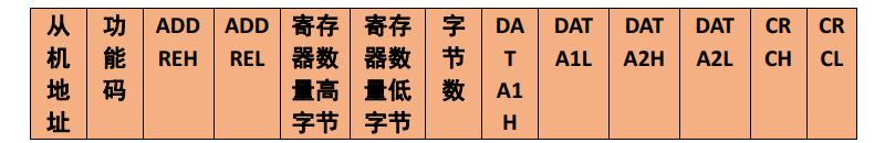
- 写多个保持寄存器10H
- 写多个保持寄存器,字节指令操作,可写多个。
- 指令
- 保持寄存器起始地址为0x0034,写2个寄存器4个字节数据
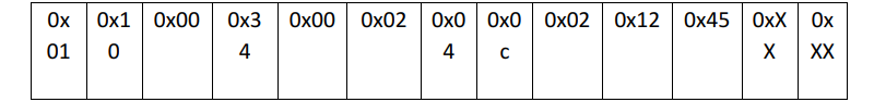
- 响应

2.RS-485介绍
- RS-485 是一种工业控制环境中常用的通讯协议,隶属于 OSI 模型物理层的电气特性规定为 2 线,半双工,多点通信的标准。它具有抗干扰能力强、传输距离远的特点。 RS-485 通讯协议由 RS-232 协议改进而来,协议层不变,只是改进了物理层,用缆线两端的电压差值来表示传递信号。RS485 仅仅规定了接受端和发送端的电气特性,它没有规定或推荐任何数据协议,因而保留了串口通讯协议应用简单的特点。
- RS485 的特点:
- ① 接口电平低,不易损坏芯片。 RS485 的电气特性:逻辑“ 1”以两线间的电压差为+(2~6)V表示;逻辑“ 0”以两线间的电压差为-(2~6)V 表示。接口信号电平比 RS232 降低了,不易损坏接口电路的芯片,且该电平与 TTL 电平兼容,可方便与 TTL 电路连接。
- ② 传输速率高。 10 米时, RS485 的数据最高传输速率可达 35Mbps,在 1200m 时,传输速度可达 100Kbps。
- ③ 抗干扰能力强。 RS485 接口是采用平衡驱动器和差分接收器的组合,抗共模干扰能力增强,即抗噪声干扰性好。 传输距离远,支持节点多。 RS485 总线最长可以传输 1200m以上(速率≤100Kbps)
- ④ 一般最大支持 32 个节点,如果使用特制的 485 芯片,可以达到 128 个或者 256 个节点,最大的可以支持到 400 个节点。RS485 推荐使用在点对点网络中,线型,总线型,不能是星型,环型网络。理想情况下 RS485需要 2 个终端匹配电阻,其阻值要求等于传输电缆的特性阻抗(一般为 120Ω)。没有特性阻抗的话,当所有的设备都静止或者没有能量的时候就会产生噪声,而且线移需要双端的电压差。没有终接电阻的话,会使得较快速的发送端产生多个数据信号的边缘,导致数据传输出错。
3.ADC介绍
- ADC是A/D转换部件,单片机不能直接处理模拟量,所以需要ADC将模拟量转换为数字量后,在进行处理。在使用单片机进行模拟数据处理的过程中,ADC至关重要。ADC以下几种类型:
- 积分型:积分型AD工作原理是将输入电压转换成时间(脉冲宽度信号)或频率(脉冲频率),然后由定时器/计数器获得数字值。其优点是用简单电路就能获得高分辨率,抗干扰能力强,但缺点是由于转换精度依赖于积分时间,因此转换速率极低。初期的单片AD转换器大多采用积分型,现在逐次比较型已逐步成为主流。
- 逐次比较型:逐次比较型AD由一个比较器和DA转换器通过逐次比较逻辑构成,从MSB开始,顺序地对每一位将输入电压与内置DA转换器输出进行比较,经n次比较而输出数字值。其电路规模属于中等。其优点是速度较高、功耗低,在低分辨率(<12位)时价格便宜,但高精度(>12位)时价格很高。
- 并行比较型/串并行比较型:并行比较型AD采用多个比较器,仅作一次比较而实行转换,又称FLash(快速)型。由于转换速率极高,n位的转换需要2n-1个比较器,因此电路规模也极大,价格也高,只适用于视频AD转换器等速度特别高的领域。串并行比较型AD结构上介于并行型和逐次比较型之间,最典型的是由2个n/2位的并行型AD转换器配合DA转换器组成,用两次比较实行转换,所以称为 Half flash(半快速)型。还有分成三步或多步实现AD转换的叫做分级(Multistep/Subrangling)型AD,而从转换时序角度又可称为流水线(Pipelined)型AD,现代的分级型AD中还加入了对多次转换结果作数字运算而修正特性等功能。这类AD速度比逐次比较型高,电路 规模比并行型小。
- Σ-Δ(Sigma delta)调制型:Σ-Δ型AD由积分器、比较器、1位DA转换器和数字滤波器等组成。原理上近似于积分型,将输入电压转换成时间(脉冲宽度)信号,用数字滤波器处理后得到数字值。电路的数字部分基本上容易单片化,因此容易做到高分辨率。主要用于音频和测量。
- 电容阵列逐次比较型:电容阵列逐次比较型AD在内置DA转换器中采用电容矩阵方式,也可称为电荷再分配型。一般的电阻阵列DA转换器中多数电阻的值必须一致,在单芯片上生成高 精度的电阻并不容易。如果用电容阵列取代电阻阵列,可以用低廉成本制成高精度单片AD转换器。最近的逐次比较型AD转换器大多为电容阵列式的。
- 压频变换型:压频变换型(Voltage-Frequency Converter)是通过间接转换方式实现模数转换的。其原理是首先将输入的模拟信号转换成频率,然 后用计数器将频率转换成数字量。从理论上讲这种AD的分辨率几乎可以无限增加,只要采样的时间能够满足输出频率分辨率要求的累积脉冲个数的宽度。其优点是分辨率高、功耗低、价格低,但是需要外部计数电路共同完成AD转换。
- ADC主要参数介绍
- ADC主要参数有以下几点:
- 分辨率:数字量变化一个最小量时模拟量的变化量,定义为满刻度与2n的比值。分辨率又称精度,通常以数字信号的位数来表示。
- 转换速率:完成一次A/D转换所需要时间的倒数,值越大表示转换得越快。积分型AD的转换时间是毫秒级属低速AD,逐次比 较型AD是微秒级属中速AD,全并行/串并行型AD可达到纳秒级。
- 量化误差:由于AD的有限分辨率而引起的误差,即有限分辨率AD的阶梯状转移特性曲线与无限分辨率AD(理想AD)的转移特 性曲线(直线)之间的最大偏差。通常是1 个或半个最小数字量的模拟变化量,表示为1LSB、1/2LSB。
- 偏移误差:输入信号为零时输出信号不为零的值,可外接电位器调至最小。
- 满刻度误差:满度输出时对应的输入信号与理想输入信号值之差。
- 线性度:实际转换器的转移函数与理想直线的最大偏移。
- STM32H750 ADC介绍
- STM32H750xx系列有3个ADC,都可以独立工作,其中ADC1和ADC2还可以组成双重模式(提高采样率)。STM32H750的ADC分辨率高达16位,每个ADC具有多达20个的采集通道,这些通道的A/D转换可以单次、连续、扫描或间断模式执行。ADC的结果可以左对齐或右对齐方式存储在32位数据寄存器中。
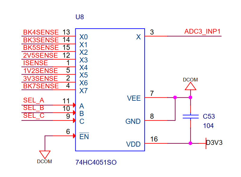
4.74HC4051介绍
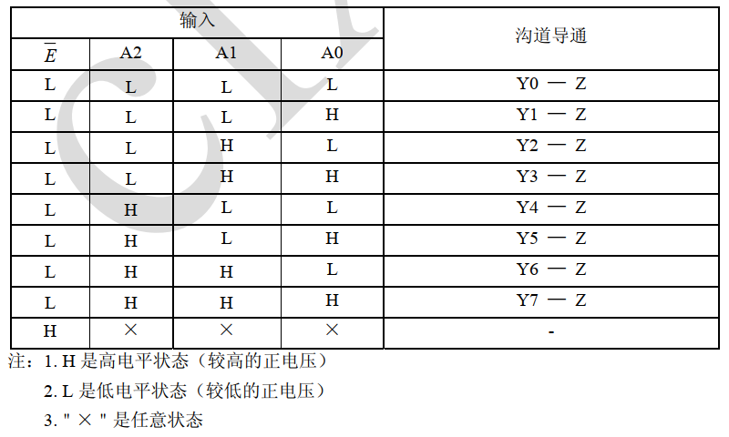
- 74HC4051是一款八选一模拟开关电路,内置3个地址选择端(A0~A2),低有效的使能输入端(E ̅),8路独立的输入/输出端(Y0~Y7)及公共输入/输出端(Z)。
- 电路内部有8个双向模拟开关,每个开关的一端连接到独立的输入/输出(Y0~Y7)端,另一端连接到公共的输入/输出(Z)端。
- 当E ̅为低电平时,通过A0~A2选择一个通路的开关处于低阻导通状态。当E ̅为高电平时,A0~A2设置无效,所有开关处于高阻关断状态。如果需要切换开关状态,就必须使用使能输入端(E ̅)。
- VDD和VSS是连接到数字控制输入端(A0~A2和E ̅)的电源电压。(VDD-VSS)的范围是3~9V。模拟输入输出(Y0~Y7和Z)能够在最高VDD,最低VEE之间变化。VDD-VEE不会超过9V。对于用做数字多路选择开关,VEE和VSS是连在一起的(通常接地)。
- 74HC4051主要应用于模拟多路选择开关、数字多路选择开关及信号选通。
- 逻辑图:

- 功能说明:
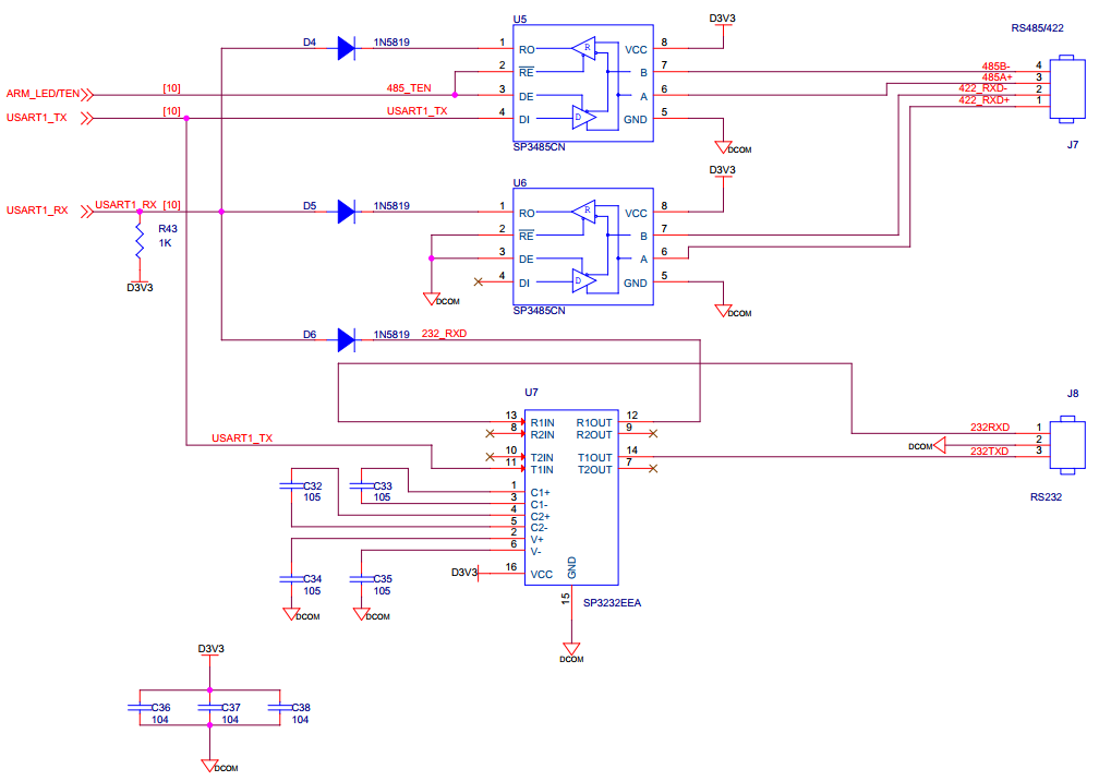
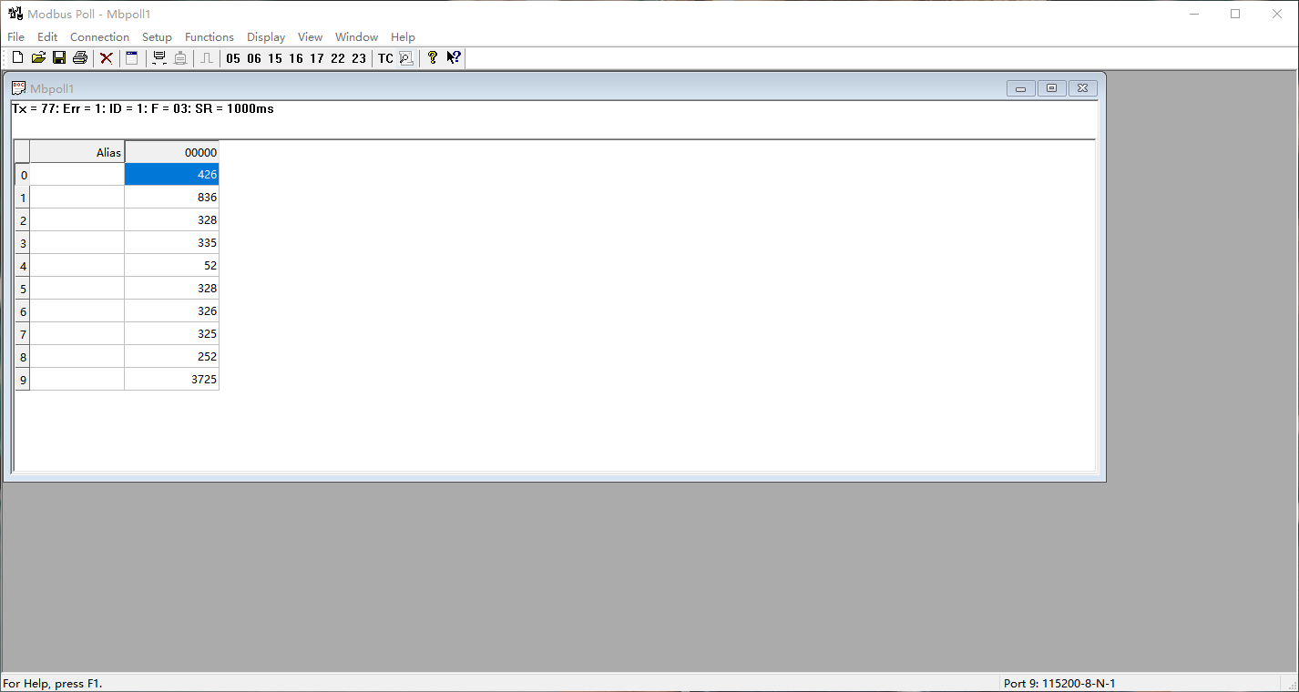
- 在本实验中,我们的计算机通过转接模块连接iCore4T的RS-485,通过Modbus Poll软件获得iCore4T的电源电压和温度信息。
- 原理图:
四、实验程序
1.主函数
int main(void)
{
    int i;
    unsigned short int temp[10] = {0};
    HAL_Init();
    SystemClock_Config();
    i2c.initialize();
    axp152.initialize();
    axp152.set_dcdc1(3500);//[ARM & FPGA]
    axp152.set_dcdc2(1200);//[FPGA INT]
    axp152.set_dcdc3(3300);//[DCOUT3]
    axp152.set_dcdc4(3300);//[DCOUT4]

    axp152.set_aldo1(3300);//[BK3]
    axp152.set_aldo2(3300);//[ALDOOUT2]
    axp152.set_dldo1(3300);//[BK0]
    axp152.set_dldo2(3300);//[BK1]
    HAL_Delay(200);


    MX_GPIO_Init();
    MX_USART1_UART_Init();
    MX_ADC1_Init();
    MX_ADC3_Init();

    usart1.initialize(115200);

  while (1)
  {
        if(_500ms_flag == 1){
            _500ms_flag = 0;
            my_adc.read(0);
            my_adc.read_mux();
            temp[0] = my_adc.value[0] * 6 * 100;  //5V监控 放大100倍
            temp[1] = my_adc.value[5] / 2 * 1000.;//电流监控,取整
            temp[2] = my_adc.value[7] * 2 * 100;  //3.3V监控 放大100倍
            temp[3] = my_adc.value[4] * 2 * 100;  //2.5V监控 放大100倍
            temp[4] = my_adc.value[6] * 100;      //1.2V监控 放大100倍
            temp[5] = my_adc.value[2] * 2 * 100;  //BK3监控 放大100倍
            temp[6] = my_adc.value[1] * 2 * 100;  //BK4监控 放大100倍
            temp[7] = my_adc.value[3] * 2 * 100;  //BK5监控 放大100倍
            temp[8] = my_adc.value[8] * 2 * 100;  //BK7监控 放大100倍
            temp[9] = lm75.read()*100;            //温度监控 放大100倍
            for(i = 0;i < 10;i ++){
                hold_reg[2*i + 0] = temp[i] >> 8;
                hold_reg[2*i + 1] = temp[i] & 0xFF;
            }
        }
        if(_100ms_flag == 1){
            _100ms_flag = 0;
            modbus.process();
        }
  }
}
2.Modbus相关函数
static char process(void)
{
  unsigned short temp;
  unsigned char receive_buffer_temp[140];
  int counter_temp;

  //crc
  if(usart1.counter < 2)return 0;
  counter_temp = usart1.counter;
  usart1.counter = 0;

  memcpy(receive_buffer_temp,usart1.receive_buffer,counter_temp);
  memset(usart1.receive_buffer,0,counter_temp);

  temp = receive_buffer_temp[counter_temp - 1] << 8|receive_buffer_temp[counter_temp - 2];
  if(crc(receive_buffer_temp,counter_temp - 2) == temp)mb_rsq_pdu(receive_buffer_temp,counter_temp);

  return 0;
}

static int mb_rsq_pdu(unsigned char *receive_buffer_temp,int counter_temp)
 {
   if(receive_buffer_temp[0] == mb_slave_address){
     switch(receive_buffer_temp[1]){
       case 1:
               function_1(receive_buffer_temp);
               break;
       case 2:
               function_2(receive_buffer_temp);
               break;
       case 3:
               function_3(receive_buffer_temp);
               break;
       case 4:
               function_4(receive_buffer_temp);
               break;
       case 5:
               function_5(receive_buffer_temp,counter_temp);
               break;
       case 6:
               function_6(receive_buffer_temp,counter_temp);
               break;
       default :
               mb_excep_rsq_pdu(receive_buffer_temp,1);
               break;
     }
  }else if(receive_buffer_temp[0] == 0){
      broadcast(receive_buffer_temp);
    }
  return 0;
 }

static int function_1(unsigned char *receive_buffer_temp)
{
  int i;
  unsigned short cnt;
  unsigned short coil_num;
  unsigned short start_address;
  unsigned short crc_value;
  int temp;

  start_address = (receive_buffer_temp[2] << 8) | receive_buffer_temp[3];

  coil_num = receive_buffer_temp[4] << 8| receive_buffer_temp[5];

  if((start_address + coil_num) > 255){
    mb_excep_rsq_pdu(receive_buffer_temp,2);
    return 1;
  }

  receive_buffer_temp[2] = ((coil_num % 8 )? (coil_num / 8 + 1) : (coil_num / 8));
  cnt = receive_buffer_temp[2] + 5;
  if(coil_num % 8){
    if(coil_num < 8){
      for(i = 0;i < coil_num;i ++)temp |= 1 << i;
      receive_buffer_temp[3] = ((coil[start_address / 8]) >> (start_address % 8) | (coil[start_address / 8 + 1]) << (8 - (start_address % 8))) & temp;
    }else {
      for(i = 0;i < receive_buffer_temp[2] - 1;i++)receive_buffer_temp[3 + i] = (coil[i + start_address / 8]) >> (start_address % 8) | (coil[i + start_address / 8 + 1]) << (8 - (start_address % 8));
      receive_buffer_temp[3 + i] = (coil[i + start_address / 8] << ((8 - (coil_num % 8 - start_address % 8) % 8)) & 0xff) >> (8 - (coil_num % 8));
    }
  }else {
      for(i = 0;i < receive_buffer_temp[2];i++)receive_buffer_temp[3 + i] = (coil[i + start_address / 8]) >> (start_address % 8) | (coil[i + start_address / 8 + 1]) << (8 - (start_address % 8));
  }

  crc_value = crc(receive_buffer_temp,cnt - 2);
  receive_buffer_temp[cnt - 2] = crc_value & 0x00ff;
  receive_buffer_temp[cnt - 1] = (crc_value >> 8) & 0xff;

  for(i = 0;i < cnt;i++)usart1.send_byte(receive_buffer_temp[i]);

  return 0;
}

static int function_3(unsigned char *receive_buffer_temp)
{
  int i;
  int cnt;
  unsigned short int start_address;
  unsigned short int crc_value;

  start_address = (receive_buffer_temp[2] << 8) | receive_buffer_temp[3];

  receive_buffer_temp[2] = receive_buffer_temp[5] * 2;

  if(receive_buffer_temp[2] > 100){ //判断最大传输量,防止越界
    mb_excep_rsq_pdu(receive_buffer_temp,2);
    return 1;
  }

  if((start_address * 2 + receive_buffer_temp[2]) > 512){
    mb_excep_rsq_pdu(receive_buffer_temp,2);
    return 1;
  }

  cnt = receive_buffer_temp[2] + 5;
  for(i = 0;i < receive_buffer_temp[2];i++)receive_buffer_temp[i + 3] = hold_reg[start_address * 2 + i];

  crc_value = crc(receive_buffer_temp,cnt - 2);
  receive_buffer_temp[cnt - 2] = crc_value & 0x00ff;
  receive_buffer_temp[cnt - 1] = (crc_value >> 8) & 0xff;

  for(i = 0;i < cnt;i++)usart1.send_byte(receive_buffer_temp[i]);

  return 0;
}

static int function_5(unsigned char *receive_buffer_temp,int counter_temp)
{
  int i;
  unsigned short start_address;

  start_address = (receive_buffer_temp[2] << 8) | receive_buffer_temp[3];

  if(start_address > 255){
    mb_excep_rsq_pdu(receive_buffer_temp,2);
    return 1;
  }

  if((receive_buffer_temp[4] == 0xff) && (receive_buffer_temp[5] == 0x00)){
     coil[(start_address / 8)] |= 1 << start_address % 8;
  }else if((receive_buffer_temp[4] == 0x00) && (receive_buffer_temp[5] == 0x00)){
     coil[(start_address / 8)] &= ~(1 << start_address % 8);
  }else {
     mb_excep_rsq_pdu(receive_buffer_temp,3);
  }

  for(i = 0;i < counter_temp;i++){
     usart1.send_byte(receive_buffer_temp[i]);
  }
  return 0;
3.74HC4051通道配置
//定义74HC4051片选管脚
#define SEL_A_ON  HAL_GPIO_WritePin(GPIOI, SEL_A_Pin, GPIO_PIN_SET)
#define SEL_A_OFF HAL_GPIO_WritePin(GPIOI, SEL_A_Pin, GPIO_PIN_RESET)

#define SEL_B_ON  HAL_GPIO_WritePin(GPIOI, SEL_B_Pin, GPIO_PIN_SET)
#define SEL_B_OFF HAL_GPIO_WritePin(GPIOI, SEL_B_Pin, GPIO_PIN_RESET)

#define SEL_C_ON  HAL_GPIO_WritePin(GPIOI, SEL_C_Pin, GPIO_PIN_SET)
#define SEL_C_OFF HAL_GPIO_WritePin(GPIOI, SEL_C_Pin, GPIO_PIN_RESET)
//选择测量BK4时片选脚状态
#define CHANNEL_0_ON SEL_C_OFF;\
                     SEL_B_OFF;\
                     SEL_A_OFF
//选择测量BK3时片选脚状态
#define CHANNEL_1_ON SEL_C_OFF;\
                     SEL_B_OFF;\
                     SEL_A_ON
//选择测量BK5时片选脚状态
#define CHANNEL_2_ON SEL_C_OFF;\
                     SEL_B_ON;\
                     SEL_A_OFF
//选择测量2.5V时片选脚状态
#define CHANNEL_3_ON SEL_C_OFF;\
                     SEL_B_ON;\
                     SEL_A_ON
//选择测量输入电流时片选脚状态
#define CHANNEL_4_ON SEL_C_ON;\
                     SEL_B_OFF;\
                     SEL_A_OFF
//选择测量1.2V时片选脚状态
#define CHANNEL_5_ON SEL_C_ON;\
                     SEL_B_OFF;\
                     SEL_A_ON
//选择测量3.3V时片选脚状态
#define CHANNEL_6_ON SEL_C_ON;\
                     SEL_B_ON;\
                     SEL_A_OFF
//选择测量BK7时片选脚状态
#define CHANNEL_7_ON SEL_C_ON;\
                     SEL_B_ON;\
                     SEL_A_ON
4.ADC初始化函数
void MX_ADC1_Init(void)
{
  ADC_MultiModeTypeDef multimode = {0};
  ADC_ChannelConfTypeDef sConfig = {0};
  hadc1.Instance = ADC1;
  hadc1.Init.ClockPrescaler = ADC_CLOCK_ASYNC_DIV16;  //16分频
  hadc1.Init.Resolution = ADC_RESOLUTION_16B;  //ADC转换分辨率16位
  hadc1.Init.ScanConvMode = ADC_SCAN_DISABLE;  //非扫描模式
  hadc1.Init.EOCSelection = ADC_EOC_SINGLE_CONV;  //关闭 EOC 中断
  hadc1.Init.LowPowerAutoWait = DISABLE;  //自动低功耗关闭
  hadc1.Init.ContinuousConvMode = DISABLE;  //关闭连续转换
  hadc1.Init.NbrOfConversion = 1;	//1个转换在规则序列中
  hadc1.Init.DiscontinuousConvMode = DISABLE;  //禁止不连续采样模式
  hadc1.Init.ExternalTrigConv = ADC_SOFTWARE_START;  //软件触发
  hadc1.Init.ExternalTrigConvEdge = ADC_EXTERNALTRIGCONVEDGE_NONE;  //禁止触发检测
  hadc1.Init.ConversionDataManagement = ADC_CONVERSIONDATA_DR; //存到DR寄存器
  hadc1.Init.Overrun = ADC_OVR_DATA_PRESERVED;  //溢出保留上次转换数据
  hadc1.Init.LeftBitShift = ADC_LEFTBITSHIFT_NONE;  //位数不左移
  hadc1.Init.OversamplingMode = DISABLE;  //关闭过采样
  if (HAL_ADC_Init(&hadc1) != HAL_OK)
  {
    Error_Handler();
  }
  multimode.Mode = ADC_MODE_INDEPENDENT; //独立模式
  if (HAL_ADCEx_MultiModeConfigChannel(&hadc1, &multimode) != HAL_OK)
  {
    Error_Handler();
  }
  sConfig.Channel = ADC_CHANNEL_16;  //通道16
  sConfig.Rank = ADC_REGULAR_RANK_1;  //第 1 个序列
  sConfig.SamplingTime = ADC_SAMPLETIME_1CYCLE_5;  //采样时间
  sConfig.SingleDiff = ADC_SINGLE_ENDED;  //单端输入
  sConfig.OffsetNumber = ADC_OFFSET_NONE;  //不选择偏移序号
  sConfig.Offset = 0;
  if (HAL_ADC_ConfigChannel(&hadc1, &sConfig) != HAL_OK)
  {
    Error_Handler();
  }

void MX_ADC3_Init(void)
{
  ADC_ChannelConfTypeDef sConfig = {0};
  hadc3.Instance = ADC3;
  hadc3.Init.ClockPrescaler = ADC_CLOCK_ASYNC_DIV16;
  hadc3.Init.Resolution = ADC_RESOLUTION_16B;
  hadc3.Init.ScanConvMode = ADC_SCAN_DISABLE;
  hadc3.Init.EOCSelection = ADC_EOC_SINGLE_CONV;
  hadc3.Init.LowPowerAutoWait = DISABLE;
  hadc3.Init.ContinuousConvMode = DISABLE;
  hadc3.Init.NbrOfConversion = 1;
  hadc3.Init.DiscontinuousConvMode = DISABLE;
  hadc3.Init.ExternalTrigConv = ADC_SOFTWARE_START;
  hadc3.Init.ExternalTrigConvEdge = ADC_EXTERNALTRIGCONVEDGE_NONE;
  hadc3.Init.ConversionDataManagement = ADC_CONVERSIONDATA_DR;
  hadc3.Init.Overrun = ADC_OVR_DATA_PRESERVED;
  hadc3.Init.LeftBitShift = ADC_LEFTBITSHIFT_NONE;
  hadc3.Init.OversamplingMode = DISABLE;
  if (HAL_ADC_Init(&hadc3) != HAL_OK)
  {
    Error_Handler();
  }
  sConfig.Channel = ADC_CHANNEL_1;
  sConfig.Rank = ADC_REGULAR_RANK_1;
  sConfig.SamplingTime = ADC_SAMPLETIME_1CYCLE_5;
  sConfig.SingleDiff = ADC_SINGLE_ENDED;
  sConfig.OffsetNumber = ADC_OFFSET_NONE;
  sConfig.Offset = 0;
  if (HAL_ADC_ConfigChannel(&hadc3, &sConfig) != HAL_OK)
  {
    Error_Handler();
  }
}
5.ADC读取函数
void sort(unsigned short int a[], int n)
{
    int i, j, t;

    //元素从小到大排列
    for (i = 0; i < n - 1; i++) {
        for (j = 0; j < n - i - 1; j++) {
            if (a[j] > a[j + 1]) {
                t = a[j];
                a[j] = a[j + 1];
                a[j + 1] = t;
            }
        }
    }
}

int read(int channel)
{
    int i;
    unsigned long int temp = 0;
    unsigned short int data[50];
    ADC_ChannelConfTypeDef channel_config;
    int channel_remap[2] = {ADC_CHANNEL_16,ADC_CHANNEL_1};//ADC1,16通道

    channel_config.Channel = channel_remap[channel]; //通道选择
    channel_config.Offset = 0; //偏移量为0
    channel_config.Rank = ADC_REGULAR_RANK_1; //第一个序列
    channel_config.SamplingTime = ADC_SAMPLETIME_1CYCLE_5; //采样时间
channel_config.SingleDiff = ADC_SINGLE_ENDED; //单端输入
     channel_config.OffsetNumber = ADC_OFFSET_NONE;  //不选择偏移序号

    for(i = 0;i < 50;i ++){
        if(channel == 0){ //如果通道为0,则使能ADC1
            HAL_ADC_ConfigChannel(&hadc1,&channel_config);
            HAL_ADC_Start(&hadc1);
            while(!__HAL_ADC_GET_FLAG(&hadc1,ADC_FLAG_EOC));
            data[i] = HAL_ADC_GetValue(&hadc1);
        }else if(channel == 1){ //如果通道为1,则使能ADC3
            HAL_ADC_ConfigChannel(&hadc3,&channel_config);
            HAL_ADC_Start(&hadc3);
            while(!__HAL_ADC_GET_FLAG(&hadc3,ADC_FLAG_EOC));
            data[i] = HAL_ADC_GetValue(&hadc3);
        }
    }

    sort(data,50);
    for(i = 20;i < 30;i++){ //取ADC排序后的中间10位数值
        temp += data[i];
    }

    temp = temp / 10; //取ADC平均值
    if(channel == 0){ //读取ADC1的值
        my_adc.value[channel] = temp * ADC_REF / 65536;
    }

    return temp;
}

static int read_mux(void)
{	//打开通道并读取ADC的值
    CHANNEL_0_ON;
    my_adc.value[1] = my_adc.read(1) * ADC_REF / 65536;

    CHANNEL_1_ON;
    my_adc.value[2] = my_adc.read(1) * ADC_REF / 65536;

    CHANNEL_2_ON;
    my_adc.value[3] = my_adc.read(1) * ADC_REF / 65536;

    CHANNEL_3_ON;
    my_adc.value[4] = my_adc.read(1) * ADC_REF / 65536;

    CHANNEL_4_ON;
    my_adc.value[5] = my_adc.read(1) * ADC_REF / 65536;

    CHANNEL_5_ON;
    my_adc.value[6] = my_adc.read(1) * ADC_REF / 65536;

    CHANNEL_6_ON;
    my_adc.value[7] = my_adc.read(1) * ADC_REF / 65536;

    CHANNEL_7_ON;
    my_adc.value[8] = my_adc.read(1) * ADC_REF / 65536;

    return 0;
}
五.实验步骤
- 把仿真器与iCore4TX的SWD调试口相连(直接相连或者通过转接器相连);
- 把iCore4TX通过Micro USB线与计算机相连,为iCore4TX供电;
- 打开 Keil MDK 开发环境,并打开本实验工程;
- 烧写程序到 iCore4TX 上;
- 也可以进入Debug 模式,单步运行或设置断点验证程序逻辑。
六.实验现象
- 通过Modbus Poll软件获得iCore4TX的电源电压和温度信息。
附录:
1、选择相应的位(32 位或 64 位)双击,NEXT→NEXT→Install→NEXT→Finished。
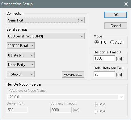
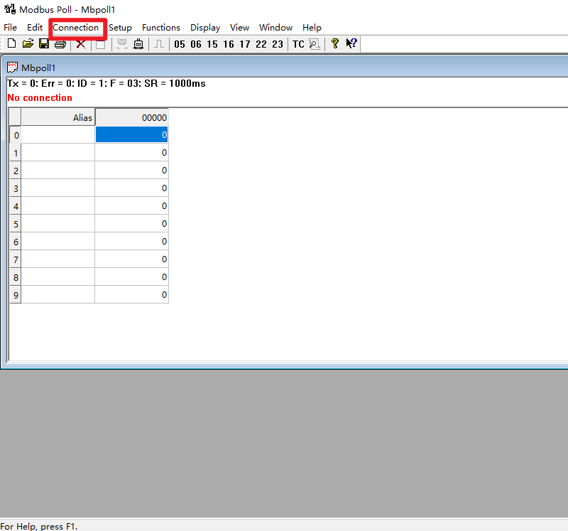
2、打开 Modbus Poll,点击 Connection connect,输入 SN.txt 中的序列号。
 3、按下图进行设置,点击 OK 即可。